Characterization of the process of smelting cast iron. What is required for smelting cast iron. Restore other items
The invention relates to the field of metallurgy, and more specifically to methods of smelting cast iron in cupola furnaces. Before the accumulation of cast iron, the letka is preheated with liquid cast iron containing 3.5 - 4.4% C, 0.9 - 2.2% Si, 0.4 - 2% Mn, with a volume equal to where dk is the diameter of the piggy bank, the heating of the holes is carried out simultaneously with the supply of oxygen to the liquid cast iron, which is carried out in the pre-discharge space of the piggy bank.
In addition, the size of these loading inlet openings 4 and 5 is designed so that they can be opened, while the furnace maintains positive pressure, which allows the dust and smoke generated in the furnace to be released, as well as to charge the raw materials at such a positive pressure .
How the blast furnace works
During rotation, buckets 11 and 12 can distribute granular raw materials on both sides of the electrode line. The shape of the feed holes 4 and 5 does not always have to be triangular, but may also be square, semicircular, or other shape. As for the charging method, any direct and continuous charging systems, such as conveyor systems, as well as the aforementioned charging system, which relies on the reciprocating movement of the buckets, will be performed.
The invention relates to the field of foundry, and more specifically to methods of smelting cast iron in cupola furnaces, and in particular to methods of smelting that eliminate the "freezing" of a metal notch for the release of metal into a ladle.
A known method of melting cast iron in cupolas with a piggy bank, which includes loading the mixture, melting it, overheating of pig iron, accumulating it in the piggy bank and releasing pig iron through a metal notch (see Grachev V.A., Cherny A.A. Modern methods of cast iron melting. Saratov, 1973, p. 80-81).
In the electric arc furnace of the present invention, the upper main line 6 and the lower tube 8 usually have a rectangular cross-section, but any shape, such as a circle or an ellipse, will take place. The upper and lower side shafts 6 and 8 are made of steel plate or iron shell, lined with refractory material inside. This separation of the furnace into two parts makes it possible to construct the furnace in such a way that the lower column 8 of the furnace is placed on the stand 13 and supported by a large number of movable rollers 14, which makes it movable to facilitate the replacement or repair of the trunk.
One of the disadvantages of this method is the possibility of “freezing” of the metal notch of the piggy bank, caused by the fact that liquid metal (especially in the first melting period, when the metal is at a low temperature and the piggy bank is not heated) is cooled in the lower part of the piggy bank, in the area of \u200b\u200bthe taphole, it crystallizes congeals with the formation of "persistence". It has been established that the “freezing” of a letka in 10-20% of swimming trunks is a cause of breakdowns in swimming trunks, as a result of which, as a rule, the cupola has to be stopped, cooled, the door of the piggy bank opened, and the crust is removed from the piggy bank, which is a very time-consuming and expensive operation.
In addition, since the lower main pipe 8 is used continuously for melting and refining, it undergoes severe wear compared to the upper furnace body. The above design when replacing the bottom wall pipe of the furnace increases operating efficiency and reduces repair costs of the furnace. However, the furnace can also be built as a whole without separation into the upper and lower trunks 6 and 8 of the furnace, when desired.
A hole for threading and its nose 7 are provided on the lower housing 8 of the furnace opposite the loading inlet openings 4 and 5 provided on the upper barrel of the furnace. The structure and position of the outlet hole and its spout 7 form a siphon system, the tap of which is at the same level as the bottom of the furnace, as shown in the drawings. This design facilitates the continuous injection of molten metal from the hearth of the furnace 26, where the molten metal collects drop by drop after it has been compressed by an arc and passes through a pre-prepared slag filtration layer.
There are a number of production methods with "freezing" of the tap hole, which are ineffective, although they are used in the smelting process. These include punching a “frozen” tap hole with a metal crowbar, burning a tap hole with oxygen, and pre-heating the piggy bank. The first dose in 50-60% of cases does not give the desired effect or leads to breakage of the flying brick. The second method is carried out by supplying oxygen from the outside of the summer brick and also does not always lead to the opening of the notch, since the effect of oxygen on an already frozen metal with a low temperature does not stimulate its oxidation and breakthrough of the notch. The oxygen consumption, as a rule, is very large, the process from the point of view of labor protection is very dangerous.
Recovery and carburization of iron in a furnace
Before injection, molten metal is collected in a furnace located near the borehole. The front furnace 15 is designed on a stand or support table 16 to be easily inclined by turning the handle 17, which allows, if necessary, to remove the collected molten metal. Since the molten metal obtained by the electric arc furnace of the present invention was completely deoxidized and desulfurized, it flows easily and cools very slowly, which makes it practical for a long residue of molten metal in the front furnace. the unloading and casting of molten metal in accordance with the present invention are made much more efficient than conventional unloading and casting methods.
According to the third method, the piggy bank is heated with a gas burner through a slag notch before melting, and in the case of a “freezing” of the metal notch, it is burned with an oxygen stream from a gas-oxygen cutter placed from the side of the piggy bank trough. The "freezing" of the tap hole, as a rule, occurs during the first release of cast iron.
Long-term experience in cupola furnaces shows that the third method allows in 40-50% of cases of “freezing” of a door to prevent an emergency and restore the cupola's efficiency. However, in other cases, the method is ineffective. This is due to the fact that, firstly, when the piggy bank is heated by a gas burner through a slag notch, the lower part of the piggy bank (bottom and notch) is slightly heated, which leads to metal “freezing” in the notch area.
Video: smelting iron in a raw-cheese way
The above are the specific characteristics of the electric arc furnace of the present invention, particularly suitable for the production of molten iron. However, the furnace is not limited to molten iron, and metals such as steel and aluminum can also be molten.
Obtaining synthetic cast iron
In the above embodiment, the number 18 indicates wires for supplying electricity to the electrodes. The number 19 indicates the suspension wires for raising and lowering the electrodes. The numbers 21 and 22 indicate the devices for moving the buckets 11 or 12, respectively, which can be driven by a force externally to insert and retract the buckets from the loading holes 4, and the buckets 11 and 12 are turned over or reset by a suitable cam or guide device in the furnace thereby loading raw materials from both sides of the electrode line.
Secondly, burning a hole with oxygen is effective only if the metal overlay is in a mushy state, and the crust of the solidified metal has a thickness of 5-10 mm. Otherwise, the method is ineffective.
The aim of the present invention is to eliminate these drawbacks and to develop a method that can effectively eliminate the "freezing" of a metal notch, mainly in the initial melting period.
When using this device, raw materials in the form of scrap can be continuously loaded by melting in a furnace. The device consists mainly of two loading buckets 11 of raw material, which are designed to enter and exit through two loading inputs 4 for raw materials, and devices are provided for driving and turning buckets 1 and 12, so that these buckets enter and exit through the charging inputs 4 and 5 as an alternative. A horizontal belt conveyor 29 is provided for loading scrap into buckets 11 and two magnetic vertical belt conveyors 31 and 32 for transferring raw materials to a horizontal belt conveyor.
The problem is solved in that in the method of smelting cast iron in a cupola, including loading the charge, melting it, overheating the cast iron, storing it in the piggy bank and discharging it through a metal notch into the ladle, pre-heat the notch with molten cast iron containing 3.5- 4.4% C, 0.9-2.2% Si, 0.4-2% Mn, with a volume equal to ![]() , where d k is the diameter of the piggy bank, and the notches are heated simultaneously with oxygen being supplied to the liquid cast iron, while oxygen is supplied to the undercountry space of the piggy bank through a pipe mounted in the lining of the piggy bank door.
, where d k is the diameter of the piggy bank, and the notches are heated simultaneously with oxygen being supplied to the liquid cast iron, while oxygen is supplied to the undercountry space of the piggy bank through a pipe mounted in the lining of the piggy bank door.
Two tanks for raw materials or bins 44 and 45 are also provided for storing the material. Devices for mutually riding and dropping the loading buckets 11 and 12 include wire drums 35 and 36, which are driven by the motor 34 through the drive shaft. Since the process is the same for the two buckets, only the operation of the bucket 11 will be described in detail.
The forward movement makes the guide 39 mounted on the shaft of the bucket at the rear end of the truck 21, passing along the inner part of the guide bar or cam surface 40, forcing the bucket 11 to rotate in the furnace, unloading its contents. Guides or cam rails 40 and 41 are respectively provided to cause the buckets to rotate and fold toward the end of their forward movement. For the reverse movement of the buckets 11 and 12, a limit switch for the reversible motor is provided. Alternatively, an appropriate switch may be provided in combination with the gearbox.
The method is as follows. Before melting, the cupola and the piggy bank are heated with natural gas to a lining temperature of 1100-1400 o C. Then, a charge, calculated on receiving liquid cast iron of the following composition, is loaded into the platypus: 3.5-4.4% C; 0.9-2.2% Si; 0.4-2% Mn. The weight of the charge is calculated so as to obtain a pig iron volume equal to ![]() where d k is the diameter of the piggy bank, (m). The loaded charge is melted, overheated in a single drum (coke cupola) or in a refractory nozzle (gas cupola), after which the liquid metal flows into the piggy bank and fills its lower part. At the same time as the piggy bank is filled through the pipeline, oxygen is supplied to the liquid metal, which reacts with the metal in the pre-discharge space.
where d k is the diameter of the piggy bank, (m). The loaded charge is melted, overheated in a single drum (coke cupola) or in a refractory nozzle (gas cupola), after which the liquid metal flows into the piggy bank and fills its lower part. At the same time as the piggy bank is filled through the pipeline, oxygen is supplied to the liquid metal, which reacts with the metal in the pre-discharge space.
Smelting Tool
The number 43 indicates a manual induction exhaust clutch. The belt conveyor system for loading raw materials consists of a horizontal endless belt 29, a hopper 30 mounted at the end of the transport distance, and a dump truck or trough 42 for alternately filling the bucket 11 and bucket 12 with raw materials from the hopper.
Materials from tanks or bins 44 and 45 are transported upward on these conveyors, which must be transferred to a horizontal belt conveyor. Tanks or bunkers 44 and 45 respectively have exits 46 for raw materials having vertically sliding control plates. The use of such magnetic conveyors makes it possible to automatically separate iron from such harmful impurities as non-ferrous metals, sand and earth, when the raw materials are in powder or granular form. This is a great advantage obtained from the use of raw materials in powder or granular form.
The oxygen supply is carried out for 2-3 minutes, after which the oxygen supply is stopped and after 5-7 minutes after the cessation of its supply, the cork is opened and the liquid metal is lowered into the ladle or poured into the pit. Next, the melting is carried out in the usual way to the desired brand.
Heating letki with molten iron allows you to efficiently heat the letrick brick, prelet space, lining and hearth to a temperature of 1300-1400 o C, which eliminates the "freezing" of the subsequent metal and, therefore, eliminates the formation of plaque in the prelet space. When oxygen is supplied to the metal, the temperature of cast iron increases (up to 1500 o C) due to the electrothermal oxidation reactions of C, Si and Mn, as a result of which the temperature of the lining in the lower part rises to 1450-1500 o C. High heating of the lining in the lower part and especially summer brick due to the influence of cast iron and oxygen provides the complete elimination of the "freezing" of metal and metal tap hole. Subsequently, the tube melts and dissolves in the liquid metal.
Cast iron: melting point
Regarding the preparation of charges of raw materials, the speed of the magnetic conveyors 31 and 32 is controlled so that their magnets attract raw materials by type, such as iron cutting chips, steel cutting chips and granular iron, which can be stored separately in respective tanks 44 and 45, and so on. .
These belt conveyors for transporting raw materials and auxiliary materials can be replaced by ladle conveyors, alternating intermittently at the same speed or at different speeds. The following is an explanation of the furnace assembly and the cast iron melting method of the present invention using the electric arc furnace of the present invention.
A positive effect is achieved due to the following: 1. Heating of the tap hole with cast iron is effective, since it is carried out by the most effective type of heat transfer - heat transfer. This allows you to warm the lining to a temperature of 1300-1400 o C.
2. The use of oxygen allows you to effectively and quickly increase the temperature of cast iron to 1500 o C due to the oxidation of C, Si and Mn cast iron. The lining of the lower part of the piggy bank is also heated to the same temperature. This ultimately eliminates the possibility of the formation of metal strain in the area of \u200b\u200bthe notch.
The lower main line 8, which may have been repaired, for example, is first transferred on rollers 14 to a position directly below the upper line 6 of the furnace, extended using a jack or the like, and is tightly connected to the upper tube of the furnace. Then, the electrodes 1 are lowered to a position near the bottom of the furnace. Preserving the atmosphere in the furnace at positive pressure and strongly reducing ability, preventing the penetration of air from the outside, causes the carbon monoxide obtained during the melting process to rise through the gaps between the charged starting materials and partially reacts with the oxygen contained in the feed 23, forming carbon dioxide, which after heating the starting materials 23, it is crushed by the dust generated in the furnace through the loading inlet openings 4, and the exhaled gas and dust are collected easily and completely with On the dust cap 27 located next to the feed inlets, the 4 and 10-inch molten metal passes in droplets through a layer of slag 24 that has been prepared, filtered and cleaned by passing through layer 24 and lowered into molten metal sweat.
3. The above composition of cast iron (3.5-4.4% C; 0.9-2.2% Si; 0.4-2% Mn) provides a low melting point and, accordingly, a low crystallization temperature of cast iron (about 1150-1200 o C), which does not allow it to “freeze” at the temperatures observed in the area of \u200b\u200bthe notch. In addition, the composition described in the application is optimal from the point of view of the course of oxidation reactions of C, Si and Mn when interacting with oxygen. This is in good agreement with the practice of oxygen converters. With this composition of cast iron in 2-3 minutes, the temperature of cast iron increases from 1300 to 1500 o C. When the content of C is less than 3.5%, Si less than 0.9%, Mn less than 0.4%, the crystallization temperature of cast iron increases, its fluidity decreases, the rate of oxidation reactions decreases sharply, as a result of which the heating efficiency of the letka decreases, there is the possibility of the formation of metal deposit due to its low temperature and increased solidification temperature. The upper limit of the composition of cast iron for C, Si and Mn is limited by the difficulty of producing cast iron of this composition.
Passing through the specified slag layer 24, drops of molten steel deoxidize and desulfurize for complete purification at some point. Removing these oxides would be extremely difficult using conventional methods and furnaces. Special features of the aforementioned cast iron melting method are described in detail below.
The compressed starting materials 23 are sequentially heated from the bottom directly by means of electrodes 1, which are quickly melted into droplets of molten iron. In other words, the starting materials 23, which were charged to make such heaps around the electrodes 1, as shown in the drawings, are sequentially heated from its parts near the arcing parts of the electrodes 1, reducing their mandgetism and causing them to slide down from the sides of the electrodes 1 in section order and then to the position below the electrodes.
4. The optimal amount of pig iron in the piggy bank, equal to ![]() , provides heating of the lower part of the piggy bank over the entire height of the flying brick 230 mm. For a piggy bank with a diameter of 0.5 m, the optimal metal volume will be 0.04 m 3. The weight of the mixture will be 280 kg. If the volume of cast iron is less, then the upper part of the summer brick will not heat up, which can lead to "freezing" of the upper notch. With a larger volume, the volume of cast iron increases, the cost of its schedule increases, the oxygen consumption increases without a significant increase in the temperature of the summer brick.
, provides heating of the lower part of the piggy bank over the entire height of the flying brick 230 mm. For a piggy bank with a diameter of 0.5 m, the optimal metal volume will be 0.04 m 3. The weight of the mixture will be 280 kg. If the volume of cast iron is less, then the upper part of the summer brick will not heat up, which can lead to "freezing" of the upper notch. With a larger volume, the volume of cast iron increases, the cost of its schedule increases, the oxygen consumption increases without a significant increase in the temperature of the summer brick.
Raw materials 23, which thus fall to a position below the electrodes 1, are heated at high temperature, should be instantly melted into droplets of molten iron. Drops of molten metal turn into countless fine particles under the influence of them simultaneously with melting, and they form in a spray state, similar to precipitation, and are sent to a strongly basic layer of slag 24, which was forcibly formed under electrodes 1 to pass through the same.
In this case, the particle size of the starting materials 23 should be small enough for electric heat capacity, as described above. As for the slag layer 24, it functions not only as a filter of drops of molten metal, but also as a control or stop for drops immediately after they are received by an arc and is filtered and prevents their contact with raw materials. To this end, the slag layer 24 is formed so as to cover the entire space with respect to the lower end of the electrodes 1, the peripheral parts or the edge parts of the slag layer being turned upward to form a container for the tray, as shown in FIG. drawing.
5. The simultaneous heating of the tap hole with liquid cast iron and the supply of oxygen to the cast iron ensure the simultaneous transfer of heat from the cast iron to the lining and increase the temperature of the cast iron due to the oxidation of the elements, as a result of which the temperature of the cast iron is kept constant.
6. The oxygen supply through the pipeline to the pre-outlet space allows oxygen to be supplied to the most vulnerable place from the point of view of the formation of heat and increase the temperature of cast iron there. In the event that in the pre-launching space the formation of an infusion in the form of a semi-solidified metal nevertheless occurred, the supply of oxygen to this zone contributes to the “burning” of channels in it for the discharge of metal through the notch. Subsequently, with the steady-state melting mode, the formed nastily dissolves in the metal.
Example. Smelting was carried out in an experimental cupola with a piggy bank with a capacity of 0.5 t / h. The cupola shaft diameter is 0.5 m, the piggy bank diameter is 0.5 m. After heating it, 280 kg of charge were loaded into the cupola: 60% of pig iron, 40% of pig-iron scrap. Cast iron composition: 4.1% C, 1.5% Si, 1% Mn. The volume of pig iron obtained is 0.04 m 3. The height of its level in the piggy bank is 230 mm (to the full height of the flying brick). Cast iron was blown through the tube in the door of the piggy bank with oxygen from the cylinder for 2.0 minutes. After 5 minutes, pig iron was released from the piggy bank. The temperature of the immersion thermocouple is 1475 o C. Subsequent melting took place without "freezing" of the notch. An inspection on the production cupola confirmed the results.
Comparison of the present invention with the prototype made it possible to establish that the distinguishing features are: heating of the notches of cast iron with simultaneous purging with oxygen, the optimal composition of cast iron, its optimal volume, the supply of oxygen to the pre-outlet space. No technical solutions with the listed features in the scientific, technical and patent literature were found, which indicates a significant novelty of the invention.
Thus, the present invention has a significant novelty and positive effect. According to the invention, technological documentation is developed for implementation at the Penza Compressor Plant. The invention will find application in cupolas and other metallurgical furnaces.
A method of melting cast iron in a cupola, including loading the mixture, melting it, overheating cast iron, accumulating it in a piggy bank and releasing a piggy bank through a metal notch into a ladle, characterized in that to ensure heating of a metal watering can mainly during the initial melting period before accumulation of cast iron in the piggy bank the money-box is pre-filled with molten iron containing 3.4 - 4.4% C, 0.9 - 2.2% Si, 0.4 - 2% Mn, with a volume equal to ![]() where d to is the diameter of the piggy bank, m, simultaneously with the filling of the piggy bank with cast iron, oxygen is supplied to it through the pipeline into the pre-storage space of the piggy bank.
where d to is the diameter of the piggy bank, m, simultaneously with the filling of the piggy bank with cast iron, oxygen is supplied to it through the pipeline into the pre-storage space of the piggy bank.
Related patents:
Our time was just not called: the century of the atom, space, plastics, electronics, composites, etc., etc. In fact, our century is still iron - its alloys still make up the core of technology; the rest, although very powerful, but the periphery. The path of iron in construction, products and structures begins with the smelting of iron from ore in a blast furnace.
Note: There are almost no rich iron ores, immediately after mining suitable for smelting. The current blast furnaces operate on enriched sinter and pellets. Further in the text, ore refers to just such a raw material for ferrous metallurgy.
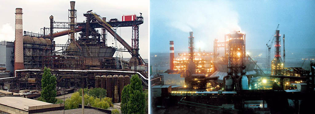
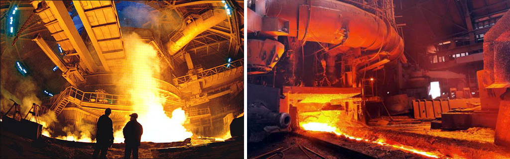
A modern blast furnace (blast furnace) is a grandiose structure up to 40 m high, weighing up to 35,000 tons and a working volume of up to 5500 cubic meters. m, issuing in one heat up to 6000 tons of cast iron. It provides operation of a blast furnace host of systems and assemblies covering an area of \u200b\u200btens and hundreds of hectares. All this economy looks impressive and in a halt with a braised blast furnace on a cloudy day, and in the work is simply enchanting. The release of cast iron from a blast furnace is also a spectacular sight, although in modern blast furnaces it no longer resembles a picture from Dante's hell.
The basic principle
The principle of operation of the blast furnace is the continuity of the metallurgical process for the entire life of the furnace until the next major overhaul, which is carried out every 3-12 years; The total service life of a blast furnace may exceed 100 years. Shaft blast furnace: from above it is periodically immersed in batches (tops) of the mixture from ore with limestone flux and coke, and molten iron is periodically released from below and the slag melt is drained, i.e. a column of raw materials in the mine blast furnace gradually settles, turning into cast iron and slag, and is built up from above. However, the path of ferrous metallurgy to this seemingly simple scheme was long and difficult.
Story
The Iron Age was replaced by the Bronze Age mainly due to the availability of raw materials. Crude iron was much inferior to bronze in everything else, including labor and cost; the latter, however, during the time of slavery, few people worried. But swamp ore, which is almost pure iron hydroxide, or rich mountain iron ore, could be found everywhere in antiquity, unlike the deposits of copper and - especially - tin, necessary to obtain bronze.
Judging by archeological data, the first iron from mineral raw materials was obtained by chance when the wrong ore was loaded into a smelter. When excavating the oldest smelters near the furnaces, sometimes clearly thrown pieces of iron cry are found (see below). The shortage of raw materials made us take a closer look at them, well, and the ancients thought, in general, no worse than us.
Initially, iron was obtained from ore by the so-called. in a cheesy way in a batch oven (not a blast furnace!). The reduction of Fe from oxides in this case occurred due to carbon fuel (charcoal). The temperature in the house did not reach the melting point of iron at 1535 degrees Celsius, and as a result of the recovery process in the house, the mass of sponge iron supersaturated with carbon — the creep — was confirmed. To extract the cricket, the domnica had to be broken, and then the cricket was compacted and literally extruded from it excess carbon, long, hard and stubbornly hammering it with a heavy hammer. From the point of view of the time, the advantages of the raw-cheese process were the ability to produce crice in a very small furnace and the high quality of the critical iron: it is stronger than cast iron and is difficult to rust. How to get iron in a raw-cheese way, see the video below.
Video: smelting iron in a raw-cheese way
China was the first, much earlier than other countries, to move from slavery to feudalism. Slave labor in production ceased to be applied there and commodity-money relations began to develop, even when Ancient Rome was firmly in the West. The raw-cheese process immediately became unprofitable, but it was no longer possible to return to bronze, it simply would not be enough. The role of flux in facilitating smelting from metal ore was known as far back as the Bronze Age, for melting iron it was only necessary to increase boost, and the Chinese by trial and error by the 4th century. n e. learned to build blast furnaces with supercharged bellows driven by a water wheel, on the left in fig.

To an identical design in the second half of the XV century. Germans came, on the right in fig. It’s completely on its own: historians trace a continuous series of improvements from the housekeeper through grooms and blauofen to the blast furnace. The main thing that German metallurgists contributed to ferrous metallurgy was the burning of high-quality coal into coke, which greatly reduced the cost of fuel for the blast furnace.
The terrible enemy of the original domain process was the so-called. kozlenie, when due to a violation of the regime of blasting or a lack of carbon in the charge, a goat "landed" in the furnace, i.e. the mixture was sintered into a continuous mass. To extract the goat, the blast furnace had to be broken. A significant historical example is indicative.
The Ural breeders Demidov, as is known, were famous for their cruelty and inhuman treatment of workers, especially since there were a lot of those who were “non-landing”, fugitive serfs and deserters. "Workers" once completely hardened, and they presented to the clerk their demands, I must say, quite modest. According to Demidov’s tradition, he literally sent them in Russian. Then the workers threatened: “Come on, come here, we’ll put a goat in the stove!” The clerk stretched out, turned pale, on his horse and - galloping away. In less than an hour (at the time of horse-drawn transport - instantly), the soared “himself” galloped on a soared horse, and on the move: “Brothers, why are you? Well, what am I doing? ”The workers repeated the demands. The owner, figuratively speaking, sat down, said “Ku!” And immediately ordered the clerk to do everything thoroughly.
Until the 19th century The blast furnaces were in fact raw-cheese: atmospheric air that was unheated and not enriched with oxygen was blown into them. In 1829, the Englishman J. B. Nilson tried to heat the blown air to just 150 degrees (having previously patented his air heater in 1828). Expense of expensive coke immediately fell by 36%. In 1857, also the Englishman E. A. Cowper (Cowper) invented regenerative air heaters, later named in his honor as Cowpers. In the coolers, the air was heated to 1100-1200 degrees due to the afterburning of the exhaust blast furnace gases. Coke consumption decreased by another 1.3-1.4 times and, which is also very important, the blast furnace with kooper was not subject to hardening: when it showed signs, which happened extremely rarely with very serious violations of the process, there was always time to inflate the furnace. In addition, in coolers, due to the partial decomposition of water vapor, the intake air was enriched with oxygen up to 23-24% versus 21% in the atmosphere. With the introduction of cooper blast furnaces, the processes in the blast furnace have achieved perfection from the point of view of thermochemistry.
Blast furnace gas immediately became a valuable secondary raw material; then they didn’t think about ecology. In order not to squander it, the blast furnace was soon supplemented with a blast furnace (see below), which allowed loading the charge and coke without releasing blast furnace gas into the atmosphere. On this, the evolution of the blast furnace basically ended; its further development went along the path of important, but particular improvements, improving technical and economic, and then environmental indicators.
Domain process
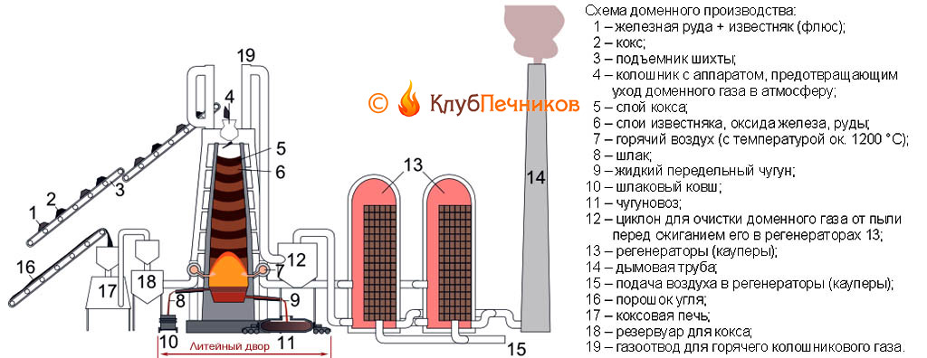
The general scheme of a blast furnace with service systems is given in Fig. The Foundry is an affiliation of small blast furnaces that produce mainly cast iron. Large blast furnaces produce over 80% of pig iron, which the pig iron immediately takes from the casting site to converter, open-hearth or electric smelters for conversion to steel. From the cast iron, molds are cast into earthen molds, as a rule, ingots - ingots - which are sent to metal manufacturers, where they are smelted for casting into products and parts in cupola furnaces. Cast iron and slag are traditionally produced through separate openings - notches, but blast furnaces of a new construction are increasingly supplied with a common notch, divided into cast iron and slag heat-resistant stove.
Note: raw iron pigs without excess carbon obtained from cast iron and intended for conversion to high-quality structural or special steel (second to fourth redistribution) are called slabs. In metallurgy, professional terminology is developed no less detailed and accurate than in the maritime industry.
At present, it seems that there are no reserves of coal and coke ovens at the blast furnaces at all. The modern blast furnace runs on imported coke. Coke oven gas is a deadly poisonous killer of ecology, but it is also the most valuable chemical raw material that must be used immediately, still hot. Therefore, by-product coke production has long stood out as a separate industry, and coke is delivered to metallurgists by transport. Which, incidentally, guarantees the stability of its quality.
How the blast furnace works
An indispensable condition for the successful operation of a blast furnace is an excess of carbon in it during the entire blast furnace process. Thermochemical (highlighted in red) and the technical and economic scheme of the domain process, see fig. Smelting of cast iron in a blast furnace occurs. way. A new blast furnace or reconstructed after a major overhaul of the 3rd category (see below) is filled with materials and ignited with gas; one of the coolers is also heated (see below). Then the air begins to blow. The coke combustion immediately increases, increasing the temperature in the blast furnace, decomposition of the flux with the release of carbon dioxide begins. Its excess in the atmosphere of the furnace with a sufficient amount of blown air does not allow coke to burn out completely, and carbon monoxide, carbon monoxide, is formed in large quantities. In this case, it is not poison, but an energetic reducing agent that greedily takes oxygen from the iron oxides that make up the ore. The reduction of iron with a gaseous monoxide, instead of a less active solid free carbon, is the fundamental difference between a blast furnace and a domnica.
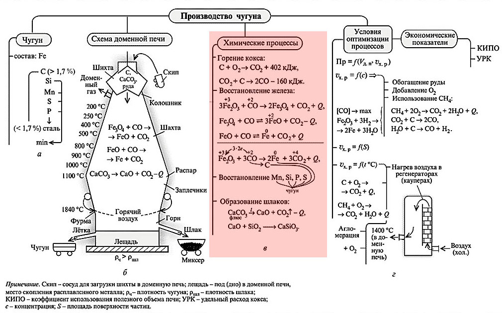
As coke burns and flux breaks up, a column of materials in the blast furnace settles. In general, a blast furnace is two truncated cones made up of bases, see below. The upper one is a mine of a blast furnace, in it iron from various oxides and hydroxides is reduced to iron monoxide FeO. The widest part of the blast furnace (the place where the bases of the cones are mated) is called steaming (steaming, steaming - wrong). At the height of the load, load settling slows down and iron is reduced from FeO to pure Fe, which is released in droplets and flows into the furnace. Ore as it were steamed, sweating with molten iron, which is why the name.
Note: the passage time of the next charge in the blast furnace from the top of the mine to the melt in the furnace is from 3 to 20 or more days, depending on the size of the blast furnace.
The temperature in the blast furnace within the loading column rises from 200-250 degrees below the top to 1850-2000 degrees in the middle. Reduced iron, flowing down, comes in contact with free carbon and is saturated with it at such temperatures. The carbon content in cast iron exceeds 1.7%, but it is impossible to beat it out, as if from critsa, from cast iron. Therefore, cast iron obtained from a blast furnace is immediately removed so that it does not spend money and resources for its remelting, it is taken away with liquid for the first redistribution into ordinary structural steel or slabs, and a blast furnace, as a rule (large and extra-large blast furnaces, is exclusive), operates as part of a metallurgical plant .
Blast furnace construction
The design of the blast furnace as a structure is given in Figure:
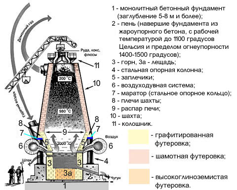
The entire blast furnace is assembled in a steel case with a wall thickness of 40 mm. In the heat-resistant stump of the blast furnace (basement, head, top of the underground foundation), a bream (under) of the cylindrical hearth is walled up. The hearth lining reaches a thickness of 1.3-1.8 m and is heterogeneous: the axial zone of the flask is lined with high-alumina brick, poorly conductive heat, and the sides with graphitized materials that have a fairly high thermal conductivity. This is necessary because the thermochemistry of the melt in the furnace has not yet "calmed down" and there is a certain excess of heat released against cooling losses. If you do not take it to the side, on a heat-resistant stump, the structure of the blast furnace will require another repair of a higher discharge (see below).
The upwardly expanding part of the blast furnace - the shoulders - is lined with graphite blocks already approx. 800 mm; the same thickness chamotte lining of the mine. Fireclay, like the lining of a forge with shoulders, is not wetted by molten slag, but closer to the latter in chemical composition. That is, the blast furnace in operation minimally overgrows with soot and holds the internal profile better, which simplifies and reduces the cost of regular repairs.
The horn and shoulders work in the most difficult conditions, excess weight loads are dangerous for them, so the blast furnace shaft rests with its shoulders (ring-shaped extension) on a strong steel ring - a marator - resting on steel columns walled in a stump. Thus, the weight loads of the forge with shoulders and shafts are transferred to the base of the blast furnace separately. Hot air from the coolers is blown into the blast furnace from an annular tubular collector with thermal insulation through special devices - tuyeres, see below. A tuyere in a blast furnace ranges from 4 to 36 (in giant blast furnaces for 8000-10 000 tons of charge and 5-6 thousand tons of cast iron per day).
Repair Discharges
The current state of the blast furnace is determined by the chemical composition of cast iron and slag. If the content of impurities approaches the limit, a blast furnace repair of the 1st category is assigned. Melts are released from the hearth, jammers are suppressed (see below), and the blast furnace is left in small breath, with a temperature inside the hearth of 600-800 degrees. Repair of the 1st category includes visual inspection, revision of the mechanical condition, measurement of the furnace profile and lining samples for chemical analysis. Once upon a time, people in special protective suits with self-contained breathing devices examined the blast furnace in small breath, now this is done remotely. After repairing the 1st category, the blast furnace can be restarted without ignition.
The result of the 1st category repair is most often (unless bad ore, flux and / or defective coke is blasted) the 2nd category repair is assigned, during which the lining is refined. Partial or complete relocation, straightening or replacement of the top apparatus are carried out in the order of repair of the 3rd category. As a rule, it is dedicated to the technical reconstruction of the enterprise, as It requires a complete shutdown, cooling of the furnace, and then its restart, ignition and restart.
Systems and equipment
The blast furnace device of a modern type includes dozens of auxiliary systems controlled by powerful computers. The metallurgists of our days still wear helmets with dark glasses, but they sit in air-conditioned cabins at the remote control with displays. Nevertheless, the principles of operation of the main systems and devices ensuring the operation of the blast furnace remained the same.
Cowpers
Kauper air heater (see. Fig.) - a cyclic device. Initially, the nozzle-regenerator of heat-resistant heat-resistant material is heated by burning blast furnace gases. When the nozzle temperature reaches approx. 1200 degrees, the Cowper switches to blowing: the outside air through it is driven into the blast furnace in countercurrent. The nozzle has cooled to 800-900 degrees - the Cowper switch again but warm up.
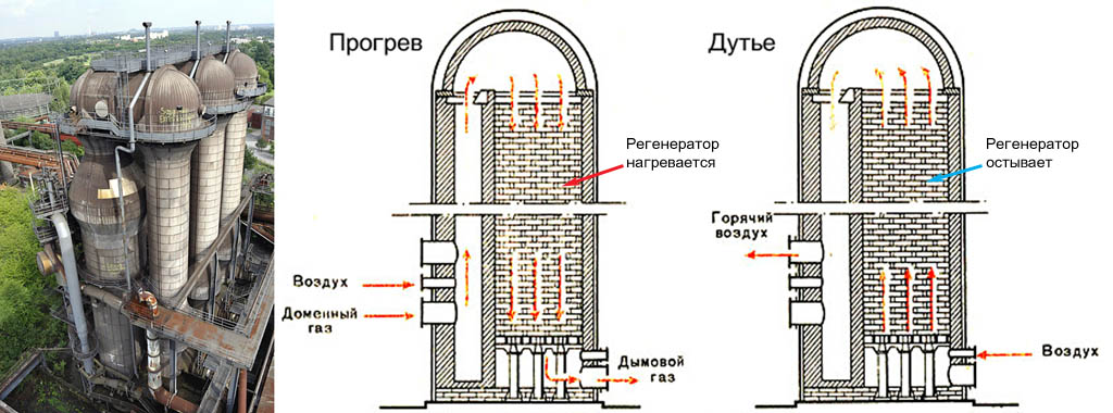
Since it is necessary to blow into the blast furnace continuously, there must be at least 2 coolers with it, but they must be built at least 3, with a margin for accident and repair. For large, super-large and giant blast furnaces, battery coolers are built from 4-6 sections.
Blast furnace
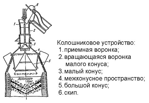
This is the most important part of the blast furnace, especially in the light of the current environmental requirements. The blast furnace top device is shown in Fig. on right; It represents 3 coordinated acting gas shutters. The cycle of his work is as follows:
- initial state - the upper cone is raised, blocks the exit to the atmosphere. The windows at the bottom of the rotating funnel fall on a horizontal partition and are closed. The lower cone is omitted, gives the output of blast furnace gases to the exhaust fan and further into the cyclone;
- the skip (see below) capsizes and dumps the top of the materials into the receiving funnel;
- a rotating funnel with windows in the bottom rotates and skips loading onto a small cone;
- a rotating funnel returns to its original state (windows are closed by a partition);
- a large cone rises, cutting off the blast furnace gases;
- the small cone drops, skipping loading into the inter-cone space;
- the small cone rises, additionally blocking the outlet to the atmosphere;
- a large cone is lowered to its original state, releasing a load into the mine blast furnace.
Thus, the materials in the shaft of the furnace lie in layers convex downward and concave from above. This is absolutely necessary for the normal operation of the blast furnace, so the lower (large) shutter is always reverse-conical. The top may be of a different design.
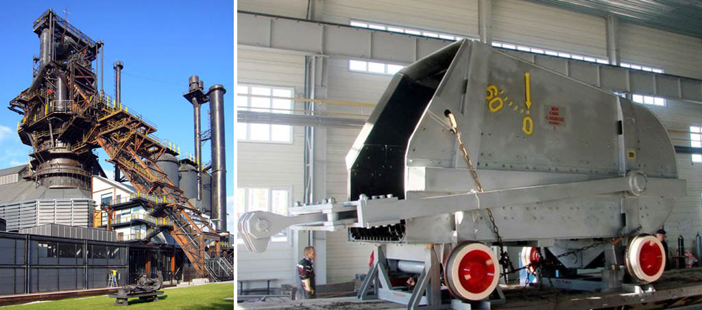
Skip
Skip, from English. - bucket, scoop, open mouth. Kolosha (with French) - a handful, a bucket, a scoop. By the way, the galoshes come from here. Blast furnaces are supplied mainly with skip material lifters. The blast furnace skip (on the right in the figure) scoops up a galosha of material from the skip pit, rises with a special mechanism along the inclined overpass (on the left in the figure), capsizes into the top furnace and returns.
Lances and tap holes
The lance of the blast furnace tuyere is shown on the left in the figure, a cast-iron notch in the center, and a slag one on the right:
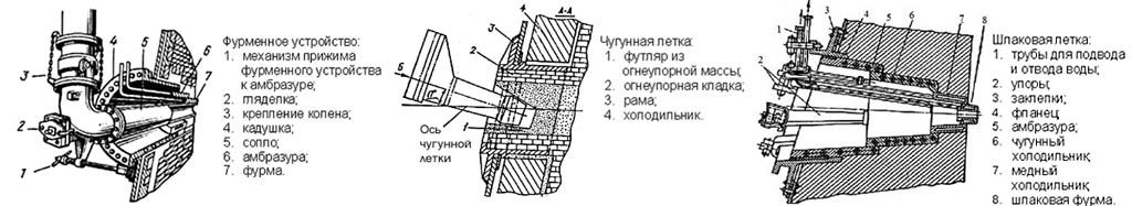
The tuyere nozzle is directed to the very heart of the blast furnace process; it is convenient to visually control its course through it, for which a peeper with heat-resistant glass is arranged on the lance duct. The air pressure at the nozzle exit of the lance is 2-2.5 ati (2.1-2.625 MPa above atmospheric). After the melt is released, the latches are sealed with a lump of heat-resistant clay. Previously, for this, they fired a plastic clay core from a special gun for this. Nowadays, seals are sealed with a remotely controlled electric gun (the name is a tribute to tradition), approaching the seashore closely. This greatly reduced the accident rate, injury risk and environmental friendliness of the blast furnace process.
Do it yourself?
Iron and steel industry is a highly profitable business. Do you know that the “rise” on it is several times higher than from gold mining? Do you think there is little oil and gas left? No, at the current rate of consumption and complete neglect of the environment, they will last another 120-150 years. But iron ore is only 30 years away. So is it possible to establish metallurgical production in your yard?
Commodity for profit - in no way. First, forget about permissions and think about it. Iron and steel industry is perhaps the main threat to the environment. An individual entrepreneur and an individual are not licensed to her anywhere, for any bribes, and the penalties for violations are harsh.
The second is raw materials. Deposits of rich ore, which can be immediately loaded into a blast furnace, there are already 2 left in the world: in Australia and Brazil. Industrial stocks of swamp ore are exhausted in antiquity, and many thousands of years are needed to restore them. There is no and will not be any agglomerate and pellets in wide sale.
In general, private ferrous metallurgy is absolutely unrealistic for the market now. Try printing better on a 3D printer. A promising thing, over time, 3D printing, if it does not completely replace metallurgy, will certainly force it out into small niches, where metal can not be dispensed with. For the environment, this will be tantamount to a reduction in hydrocarbon fuel consumption by at least 7–9 times.
Discussion topic "Blast furnace"


